This paper sets out a technical case for the buffering of wind energy variability and intermittency through the direct use of horizontal axis wind turbine work to drive compressor components in air liquefaction cycles. Open loop hydrostatic transmissions and standard torque converters are key system components that provide the necessary conversion between the low speed-high torque characteristics of the wind rotors, and lower torque and high speed characteristics required for compressors used in cryogenic plant. These, together with the other principal components for such a wind-to-cryogen device, are reviewed and compared with the components of conventional systems. The comparison extends to an economic analysis based on i) a wind turbine electricity generation model, ii) a grid-electricity-to-air compression process and iii) a compressed air to cryogen process. The process of wind rotor work-to-cryogen is compared alongside these more conventional options to reveal differences in cryogen production cost, life-cycle energy consumed and carbon savings, which motivate the investigations. The work also discusses novel options for i) integration of wind energy into energy supply systems via cryogen production, ii) wind energy storage in the form of cryogens, iii) wind energy produced cryogens as energy vectors, and iv) the novel application of a wind-to-cryogen process to provide a source of coolth to cool the ventilating air in deep mines.
I. Introduction and Motivation - Deep Mine Cooling
The development of the alternative means of provision of cooling is motivated by the exhaustion of world class surface mineral ore bodies and the consequent need to exploit deeper ore bodies using underground mining methods. Also, ore bodies that are already exploited using underground mining methods are extending workings deeper and therefore the working environment for both workers and machinery is becoming hotter. At 3,000 metres depth, the temperature of air entering ore producing areas may be 20°C to 30°C higher than the surface air temperature due to (mostly) adiabatic autocompression alone in the confined ennvironment of an air shaft. Ventilation air mass flow rates are of order 1 tonne/s in medium to large scale producing underground mines. At these depths where the virgin rock temperatures exceed 50°C in most mining areas, geothermal heat transfers will further increase the air temperature. The current methods of cooling the air centre on vapour compression refrigeration cycles, with large scale cooling towers to eject condenser heat and bulk air cooling chambers (both direct contact heat exchangers with high factors of merit as high as 0.7 to 0.8 for industrial packed towers) [1]. The ratings of the largest plants used in mines can exceed 60MWr. Refigeration plants can also be installed in the sub-surface to simplify cooling distribution, but these operate with much lower coefficients of performance due to high condenser heat reject temperatures. The cumulative effect of these circumstances is a dramatic increase in energy consumption and the cost of production of raw materials due to the introduction of these large scale refrigeration loads as mining moves deeper.
The principal desired characteristic of an alternative cooling method is thus that it should deliver cooling cheaply. Load factors of current refrigerating plants are approaching unity, or will do so, with the greater depths, so the cooling needs to be provided continuously. This means that the capital costs of cooling plant (conventional or alternative) are less important than the operating and energy input costs. This suggests the use of a renewable energy source to provide cooling because the input energy costs are close to zero. However renewable energy resources arise from natural geo-processes that are subject to natural variability and intermittency and so, whatever alternative cooling method is devised must be able to store the coolth produced while the renewable energy resource is active and used at 'on-demand' rates. The locations where the renewable energy resources are most abundant may be coincident with the locations of mineral deposits, but it must be assumed that, for the general case, they will not. Consequently, the alternative cooling method must allow for means of transportation and distribution of the cooling produced between producing areas and the consumer centres. In summary the desired characteristics are that the cooling should: be produced cheaply, be storable and be transportable and distributable.
We propose that the production of liquefied air using wind energy may be a suitable solution to the problem of providing cooling to deep mines. Wind turbines are the most mature, and largest scale technology that harnesses renewable energy. If configured for the production of liquefied air, rather than electricity, the traditional difficulties of integrating wind energy into electricity distribution grids are avoided altogther, the cooling is stored in the form of the condensed liquid, and the storage, distribution and transportation of cryogens at bulk scales also use established, mature technologies. What we discuss in the remainder of this paper is a possible configuration of a wind turbine for the production of liquefied air, rather than electricity.
II. The Simple Linde-Hampson Cycle
Carl Von Linde and William Hampson independently developed the air liquefaction cycle called the Linde-Hampson cycle in 1895 [2]. Atmospheric air is first compressed (pressure ratio typically 200) and then passed through heat exchangers to cool it down (typically lower than -150°C) after which it is allowed to expand, either through an expansion valve or an expansion turbine. In the latter instance some work can be extracted from the fluid. In either case, a proportion of the air condenses and is collected in a Dewar vessel. The remaining non-condensed air is sent to the cold side of the heat exchanger to cool the compressor delivery air and then is returned to the compressor, completing the cycle [3,4].
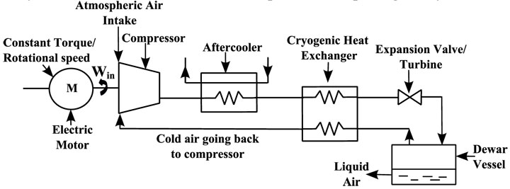
Figure 1: Schematic of the Linde-Hampson liquefaction system
The compressor, heat exchanger and expander components used in the modern air separation and liquefaction plants have been subjected to improvements in efficiency, product recovery and feed air purification over years to gain higher effectiveness than the original Linde-Hampson systems [8]. The major power consuming machines in these systems are the compressors. Therefore significant effort has been expended in improving the compressors effectiveness and the efficiency of the expanders, and to reduce the overall specific energy consumption (kWh/kg cryogen) [8]. The following table and paragraph present specific energy input consumption for various cycles for different fluids.
Table 1: Specific energy input consumption for various fluids using Linde-Hampson cycle [9]
Similarly, the specific power consumption for hydrogen liquefaction using pre-cooled Claude cycle is 12.5 to 15 kWh/kgLH2, by theoretical pre-cooled Linde-Hampson system is 64.5 to 71.7 kWh/kgLH2 and by theoretical helium-refrigerated system is 29.3 to 49.5 kWh/kgLH2 [10]. Specific energy input reported for hydrogen liquefaction in large scale Praxair, Air products and Air Linde plant systems is ~12 to 15 kWh/kgLH2; ~8.5 kWh/kgLH2 by WE-NET (with Nitrogen pre-cooled large-scale Claude plant) and 5.04 kWh/kgLH2 in four Helium Joule-Brayton cascade cycle [10].
III. Simple air liquefaction system integrated with wind turbine
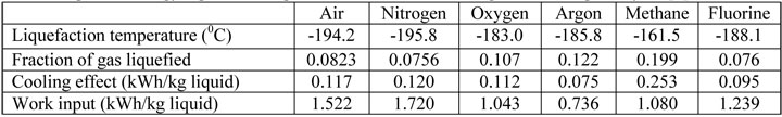
With a steady rate of work input as depicted in Figure 1, such a system may be reliably expected to produce cryogens as the Linde-Hampson cycle has been used commercially for decades. The proposed concept is to integrate wind energy capture with a cryogen production system (a cryogen is a gas/air which has a boiling point at atmospheric pressure below -1500C). This is illustrated in Figure 2. Rotational speed and torque developed by a wind turbine rotor can be highly variable and so the key question that arises is whether liquefied air would be as efficiently produced. In order to buffer the intermittency and variability of the wind energy in the very short term, an open loop hydrostatic transmission could be deployed as in Figure 2. Such a system would consist of a positive displacement hydraulic pump, a hydraulic motor, required control valves, pipes, pressurized and non-pressurized reservoirs and fittings. The motor is driven by pressurized fluid drawn from an accumulating reservoir, replenished by the pump. Thus the hydrostatic transmission can also be used to adjust and regulate wind rotor speed as described by [5], and the rotor blade tip speed ratio can be regulated to maximise efficiency over varying wind speeds. The fluid coupling of the wind rotor to the compressor is a form of torque converter equipped with energy storage.
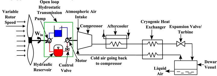
Figure 2: Schematic diagram of the proposed concept, considered installed within a wind turbine nacelle
The liquefaction system depends on the effectiveness of the heat exchangers. Compact indirect heat exchangers such as the plate and fin heat exchangers, have proven to be the most suitable for cryogenic purposes since they separate the fluid streams and have high surface area available for heat transfer [6].
There are examples of reciprocating and rotary compressors that are of positive displacement type which work by mechanically changing the volume of the working fluid. Dynamic displacement machines compress gases by mechanically changing the velocity of the working fluid and can sustain high flow rates [7]. However these compressors are open and thus there is a total loss of pressure when rotation ceases. This must be a consideration if intermittent wind energy is to drive the system, and leads directly to the adoption of a positive displacement compressor. The compression process can be considered isentropic while an experimentally determined isentropic efficiency characterises the deviation from this ideality to permit the characterisation of the state of the air after the real compression process. For multi-stage compression with intercooling and aftercooling, the compression process moves closer to an isothermal compression process, reducing the required input work.
An expansion valve, expansion engine or expansion turbine can be used to expand the air and lower its temperature and pressure, so that a fraction of it condenses. For the latter two options, isentropic processes and isentropic efficiencies can be established for analysis as for the compressors. For the expansion valve an irreversible isenthalpic process applies, with no heat or work transfer [7]. The liquefied air may be collected and stored in an insulated vessel, the Dewar vessel as mentioned above.
IV. Cost comparisons for various power generating systems using wind energy -Wind turbine installation costs
For electricity generation from wind turbines the largest constituents of the total installed development cost are the wind turbine rotor, gear box and tower which together account for 50-60%. The generator, transformer and/or power electronics and auxiliaries can account for 13%. Overall, the turbine cost is in the range of 64-84% of the development cost. According to Blanco (2009) and European Wind Energy Association, EWEA (2009), items such as grid connection, civil works, and other development costs account for the balance. However, installation and power generation costs can vary appreciably depending on the regulatory regime, installation site, and local costs for materials and services, as is illustrated in Table 2.
OECD = Organization for Economic Co-operation and Development
-Costs of various energy generating systems using wind power
The electricity generated by wind energy can be used for general purposes if the turbine is connected to an electricity distribution system. If, in the same place as the wind energy is harnessed, the design intent is to compress air for cryogen production, the generation of electricity may be an unnecessary intermediate energy conversion step [24]. The following diagrams clearly present various integration methods for energy generation using wind power. Differences in the annuitized costs along with the efficiency of each system are also presented in a paragraph that follows.
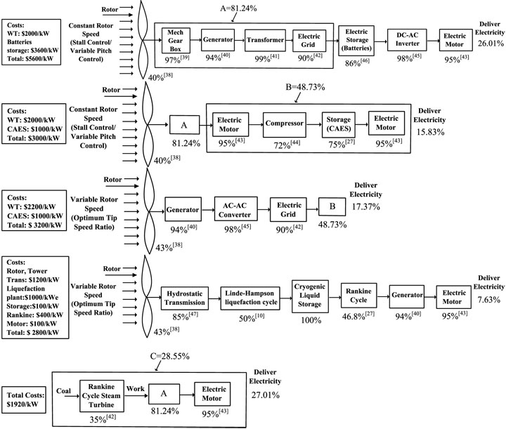
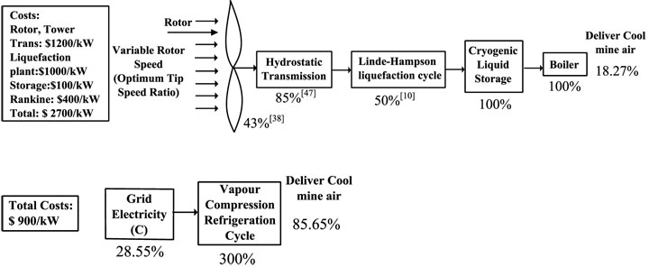
Figure 3: Schematic showing various energy generating systems using wind power with their respective costs and overall efficiencies. WT=Wind Turbine, CAES= Compressed Air Energy System
The diagrams presented above are used here for comparing different integration technologies for electricity/cooling effect generation using wind energy. All these options are compared with each other and also with the proposed Cryovent concept in terms of capital costs. The annuitized costs are also calculated with some assumptions and the references available. The overall efficiencies of each system are shown on the right, while the capital costs are given on the left side of the respective integration diagrams. All the costs except for some assumed costs are taken from the references cited in this paper.
Assumptions:
The wind turbine installation costs are taken from [34]. The average cost of a Rankine cycle generator is taken as $400/kW and that of an electric motor as $100/kW. Coal power plant electricity generation capital cost is assumed to be $1920/kW and the cryogenic liquid storage to be $100/kW for simplicity. The wind turbine installation costs are taken from [34]. The vapour compression cycle is assumed to be 300% efficient (COP=3) and the boiler is assumed to be 100% efficient. The cryogenic liquid storage is assumed to be 100% efficient [26]. The cost of liquefaction plant is calculated based on [23] & [33]. The refrigeration plant costs are calculated assuming 20MWr, with COP=3, interest rate=10%, 15 years life time, and the installation cost of $65/MWh.
Generating electricity:
- In the first power generation method, with constant rotor speed using the conventional power generation system (with gear box, generator and transformers), with battery storage, the system will be ~26.01% efficient whereas the capital cost of such an integration will be ~$5600/kW of power generated.
- In the second power generation method, again with the constant rotor speed of the wind turbine, generating power, compressing air and storing the electricity in the form of compressed air, and generating electricity on demand will be ~15.83% efficient with a capital cost of ~$3000/kW of power generated.
- The third power generation method with variable rotor speed (with optimum tip speed ratio) and the gearless generator with AC-AC converter will be ~17.3% efficient whereas the capital cost of such integration will be ~$3200/kW of power generated.
- The proposed Cryovent concept depicted in fourth diagram with a hydrostatic transmission, Linde-Hampson liquefaction system, with the storage in Dewar vessel, the power generation will be ~7.63% efficient with a total capital cost of ~$2800/kW of power generated.
- The conventional coal-fired power plant (fifth diagram) will be ~27.01% efficient for electricity production with a total capital cost of ~$1920/kW of power generated.
Delivering cool mine air:
- The proposed Cryovent concept for delivering cool mine air (sixth diagram) is calculated to be ~18.27% efficient with total capital cost of ~$2700/kW but providing some cooling as well. The annuitized cost for this system would be ~$7,900k/year with zero input energy costs. The same concept would cost ~$6,958k/year if it uses electricity to run the system with an annual input energy cost of ~$2,499k/year.
- The conventional vapor compression refrigeration plant run by the electric grid would be ~85.8% efficient with ~$900/kW total capital cost providing the same amount of cooling as Cryovent but the annuitized cost for this system would be ~$6,963k/year with an annual input energy cost of ~$3,796k/year.
V. Wind energy power generation and storage issues
The major issue with exploitation of wind energy is its variability. It can be a barrier for some processes where a continuous source of power supply is needed. Studies have been done on the storage of the variable wind energy which can offset its variability and unpredictability. Wind energy can be transformed into compressed air which can then be stored in a tank (for a small-scale), in underground abandoned mines like paste-fills or in the salt caverns (for large-scale purposes), and also in above ground reservoirs- pressure vessels [28], which can later be used on demand. However, the underground storage capacity can be affected by geological constraints [27]. Wind energy can also be stored using batteries but storing wind energy in batteries is expensive. As discussed in [24], according to Electric Power Research Institute, EPRI (2010), the total installed cost for storing wind energy by CAES is around US$125/kW/h for 8 hour duration and US$450/kW/h for lead acid storage for 4 hour duration.
Liquefied air can store wind energy compactly. 1 kg of liquefied air at atmospheric temperature stores around 440kJ of cooling (at ~ -200°C) that would be recovered through reboiling using the heat within ambient (mine ventilation) air (at ~30°C). 1m3 of liquefied air effectively stores 400MJ (111 kWh) of cooling for the same conditions. Once the cryogens are produced, they can be stored in an insulated vessel at atmospheric pressure and then transported easily. If they are produced offshore and need to be stored onshore for electricity generation later, they can be delivered onshore with no extra cost except the pumping costs. The energy density of cryogens is around 20 times higher than that of CAES. Cooling loss with cryogens stored in a Dewar vessel is principally by heat dissipation which is ~1%/day [26].
For the production of work from the stored cooling, the recovery efficiency of cryogens is as low as 36.8% with the Rankine cycle using waste heat and around 43% with combined cycle (combined Rankine and Linde cycle) at 300K. This can be compared to CAES in which the recovery efficiency is around 75%. If the compression and expansion processes are not isothermal, the recovery efficiency of the stored cryogens decreases further up to 22%. The efficiency increases to 70% when using high grade heat at 800K [27]. These figures may present a negative picture of the use of cryogens as a form of energy storage, but they are for the recovery of work from the stored heat, not the recovery of cooling capacity for which the efficiency will depend on the factor of merit of the heat exchangers.
VI. Conclusion
Integrating wind power with cryogen production process is one of the low-carbon and comparatively most economic methods to generate and store energy. Application of the energy vector produced by integrating wind energy to the liquefaction system mechanically as explained in this paper would be for several purposes. But the motivation for the development of this concept comes from the need of high-volume of ventilating air in the deep-mines. With the available natural resources being depleted in the surface, the global mining industries are acquiring the underground concept to increase the mine-operation life by some additional years. The fact that the auto-compression and geothermal gradient only add heat to the prevailing hot temperature in the underground mine working area is putting the mining industries in a constraint of having an efficient and cost-effective way for deep mine cooling and ventilation.
Use of cryogens that can be delivered by a bore-hole from surface to the sub-surface will eliminate the need of huge ventilation shafts. The cryogens also provide bulk cooling to the ventilating air during expansion. Though liquefying air is costly, the initial installment costs of such plant is offset with the two major benefits of using cryogens as compared to the conventional ventilation method for the deep mines, which are the low-cost electricity and the additional benefit of cooling. Therefore on the long run, the proposed concept of producing cryogens with the use of wind energy, storing the surplus production and using them on demand for the deep mine cooling and ventilation can be a promising way to minimize the energy costs in the mine operations.
References:
- McPherson, M. J. (2000). Subsurface Ventilation and Environmental Engineering .1625 Shaw Ave #103, Clovis, CA 93611: Mine Ventilation Services, Inc.
- Venkarathnam, G. (2008). Cryogenic mixed refrigerant processes. International Cryogenic Monograph Series.
- The Linde Group, (1879). http://www.linde-engineering.com/internet.global.lindeengineering.global/en/images/chronicle_e%5B1%5D19_9855.pdf (Accessed on 6/25/2014)
- Wankat, Phillip C., & Kostroski, Kyle P. (2010). Hybrid air separation processes for production of oxygen and nitrogen. Separation Science and Technology, 45(9), 1171-1185.
- Esposito, A. (2009). Fluid power with applications-7th edition. Upper Saddle River, New Jersey 07458: Pearson Education, Inc.
- Gupta, P., & Atrey, M. D. (2000). Performance evaluation of counter flow heat exchangers considering the effect of heat in leak and longitudinal conduction for low-temperature applications.40(7), 469-74.
- Eastop, T. D. (1993). Applied Thermodynamics for Engineering Technologists. Edinburgh Gate, Harlow, Essex CM20 2JE, England: Pearson Education.
- Castle, W. F. (2002). Air separation and liquefaction: Recent developments and prospects for the beginning of the new millennium. International Journal of Refrigeration, 25(1), 158-172. doi:http://dx.doi.org/10.1016/S0140-7007(01)00003-2
- Kanoglu, M., Dincer, I., & Rosen, M. A. (2008). Performance analysis of gas liquefaction cycles. International Journal of Energy Research, 32(1), 35-43. doi:10.1002/er.1333
- Krasae-in, S., Stang, J. H., & Neksa, P. (2010). Development of large-scale hydrogen liquefaction processes from 1898 to 2009. International Journal of Hydrogen Energy, 35(10), 4524-4533. doi:http://dx.doi.org/10.1016/j.ijhydene.2010.02.109
- McCourt, I. (1983). Hydrostatic variable speed/torque transmissions: A basic introduction. Paper presented at the Proceedings of the Conference on Drives/Motors/Controls 83, 192-5.
- Casadei, D., Serra, G., Tani, A., & Zarri, L. (2013). Direct torque control for induction machines: A technology status review.
- Bartos, J. (2006). Understand compressor types to make the right selection. Plant Engineering, 60(1), 42-5.
- Eastop, T. D. (1993). Applied Thermodynamics for Engineering Technologists. Edinburgh Gate, Harlow, Essex CM20 2JE, England: Pearson Education.
- Yeter, P., Guler, O., & Akdag, S. A. (2012). The impact of wind speed variability on wind power potential and estimated generation cost. Energy Sources, Part B (Economics, Planning and Policy), 7(4), 339-47.
- Gibescu, M., Brand, A. J., & Kling, W. L. (2009). Estimation of variability and predictability of large-scale wind energy in the Netherlands. Wind Energy, 12(3), 241-260.
- Izadian, A., Hamzehlouia, S., Deldar, M., & Anwar, S. (2014). A hydraulic wind power transfer system: Operation and modeling. IEEE Transactions on Sustainable Energy, 5(2), 457-65.
- Mason, J. E., & Archer, C. L. (2012). Baseload electricity from wind via compressed air energy storage (CAES).16(2), 1099-109.
- Nishikata S., & Tatsuta F. (2013). Studies on a Wind Turbine Generating System that Employs a Thyristor Inverter. Electrical Engineering in Japan (English Translation of Denki Gakkai Ronbunshi), 130(4), pp. 407-414.
- Yukita, K., Washizu, S., Nakano, H., Torii, A., Ueda, A., Goto, Y., & Ichiyanagi, K. (2012). A study of AC link and DC link method for wind power generation connected to electric power system. Electrical Engineering in Japan (English Translation of Denki Gakkai Ronbunshi), 178(3), pp. 21-30.
- Joselin Herbert, G. M., Iniyan, S., Sreevalsan, E., & Rajapandian, S. (2007). A review of wind energy technologies. Renewable and Sustainable Energy Reviews, 11(6), 1117-1145. doi:http://dx.doi.org/10.1016/j.rser.2005.08.004
- Milligan, M., Ela, E., Lew, D., Corbus, D., Yih-huei Wan, Hodge, B., & Kirby, B. (2012). Operational analysis and methods for wind integration studies 3(4), 612-19.
- Queneau, P. E., & Marcuson, S. W. (1996). Oxygen pyrometallurgy at copper cliff - a half century of progress. Jom, 48(1), 14-21.
- Shaw, D., Jyun-Yu Cai, & Chien-Ting Liu. (2012). Efficiency analysis and controller design of a continuous variable planetary transmission for a CAES wind energy system. Applied Energy, 100, 118-26. doi:10.1016/j.apenergy.2012.06.024.
- Dindorf, R. (2012). Estimating potential energy savings in compressed air systems. Procedia Engineering, 39(0), 204-211. doi:http://dx.doi.org/10.1016/j.proeng.2012.07.026
- Li, Y., Chen, H., Zhang, X., Tan, C., & Ding, Y. (2010). Renewable energy carriers: Hydrogen or cryogens/nitrogen? Applied Thermal Engineering, 30(14-15), 1985-1990. doi:http://dx.doi.org/10.1016/j.applthermaleng.2010.04.033
- Ameel, B., T'Joen, C., De Kerpel, K., De Jaeger, P., Huisseune, H., Van Belleghem, M., & De Paepe, M. (2013). Thermodynamic analysis of energy storage with a cryogens rankine cycle. Applied Thermal Engineering, 52(1), 130-140. doi:http://dx.doi.org/10.1016/j.applthermaleng.2012.11.037
- Safaei, H., & Keith, D. W. (2014). Compressed air energy storage with waste heat export: An alberta case study. Energy Conversion and Management, 78(0), 114-124. doi:http://dx.doi.org/10.1016/j.enconman.2013.10.043
- Deep mine cooling study, MIRARCO (2014).
- World Nuclear Association, WNA (2011) http://www.worldnuclear.org/uploadedFiles/org/WNA/Publications/Working_Group_Reports/comparison_of_lifecycle.pdf (Accessed on 6/4/2014)
- Renewable Energy Network 21, 2013 http://www.ren21.net/portals/0/documents/resources/gsr/2013/gsr2)013_lowres.pdf (Accessed on 6/4/2014)
- International Energy Agency (IEA) 2011, Wind Energy Roadmap. Retrieved from https://www.iea.org/media/workshops/2011/oao/Chandler_wind_roadmap.pdf (Accessed on 6/4/2014)
- KSH Dick Engineering, (2010). High Purity Oxygen Line: Vale Canada Limited. http://www.dickeng.com/projects/minerals-and-metals/high-purity-oxygen-line/ (Accessed on 7/6/2014)
- GL Garrad Hassan, (2012). Assessment of the estimated costs of wind energy in British Columbia. http://www.canwea.ca/pdf/Assessment_Est-Cost-of-Wind-Energy_BC.pdf (Accessed on 6/23/2014)
- The liquid air energy network. http://liquidair.org.uk/full-report/report-chapter-six/ (Accessed on 4/26/2014)
- World nuclear organization, (2001). http://www.world-nuclear.org/ (Accessed on 6/5/2014)
- The Diavik Diamond Mine, (2012). http://www.diavik.ca/ENG/ouroperations/565_wind_farm.asp (Accessed on 6/23/2014)
- Enercon wind turbines, http://www.wind-power-program.com/Library/Turbine%20leaflets/Enercon/ENERCON_Product_Overview_Eng.pdf (Accessed 7/14/2014)
- Gear Technology Magazine, www.geartechnology.com, July 2011 (Accessed on 7/9/2014)
- Grauers, A. (1996). Efficiency of three wind generator systems. http://faculty.mu.edu.sa/public/uploads/1337956177.4188loss_mech_elec..pdf (Accessed on 7/6/2014)
- Virginia transformer Corp, http://www.vatransformer.com/Transformer-Products.aspx (Accessed on 7/9/2014)
- Brown, M. A. (2014). Enhancing efficiency and renewables with smart grid technologies and policies. Futures, 58(0), 21-33. doi:http://dx.doi.org/10.1016/j.futures.2014.01.001
- Boyle, G. (1996). Renewable Energy: Power for a Sustainable Future. Walton Street, Oxford OX2 6DP, UK: Oxford University Press.
- Cuevas, C., Lebrun, J., Lemort, V., & Winandy, E. (2010). Characterization of a scroll compressor under extended operating conditions. Applied Thermal Engineering, 30(6-7), 605-615. doi:http://dx.doi.org/10.1016/j.applthermaleng.2009.11.005
- Power electronics Europe (2011) http://www.power-mag.com/ (Accessed on 7/5/2014)
- Poullikkas, A. (2013). A comparative overview of large-scale battery systems for electricity storage. Renewable and Sustainable Energy Reviews, 27(0), 778-788. doi:http://dx.doi.org/10.1016/j.rser.2013.07.017
- Hydraulics & Pneumatics, http://hydraulicspneumatics.com/hydraulic-pumps-amp-motors/hydrostatic-transmissions-power-play-wind-turbine-design (Accessed on 7/6/2014)
|